Profile machining / polygonal drilling
Polygon or free-form shapes with the Formbore system tool
Application
Application: Takes the place of reaming, erosion or milling — Changes in the work process are no longer a problem with formbore
Machine type: formbore system tools can be used on machining centres, milling, turning and special purpose machines.
Features
- no synchronous coordination to the machine necessary
- independently of the machining spindle
- blind holes without residual chips
Advantages
- enduring dimensional accuracy
- almost wear and maintenance-free
- considerable reduction of working time
- designed for many different profile shapes and sizes
Description / Qualities
As flexible and independent as convincing: For the first time you can produce a high variety of inner and outer profiles with the highest possible precision by means of simple drilling and turning processes on normal machining centres. formbore system tools are designed for different profiles and profile sizes. It is possible to make changes to the working process, for example to separate reaming, erosion or milling.
Formbore system tools reduce the working time considerably in comparison to the processes currently being used. Further advantages are blind holes without residual chips and the constant accuracy due to the correction of the cutter wear. The torque support and the modular tool holders are identical to the ones used on the Bilz GNCK / GNCN tapping attachments.
Design and mode of operation of the formbore system tools:
Formbore system tools consist of two components: drive shaft and drill chuck. The rotating drive shaft is located in the case. The torque driven control determines the movement sequence of the drill chuck. The deflection of the blade is by means of entirely rolling elements. formbore system tools therefore operate practically wearand maintenance-free and make machining of most materials up to 900 N/mm2 strength possible.
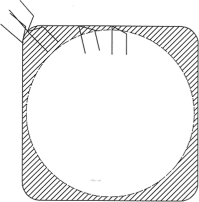
For inside processing, a formbore is initially machined up to a maximum of 0,5 mm diameter smaller than the spanner size (SQ). The actual form drilling operation is carried out in a single process with profile adjusted speed and feed appropriate to the material being machined. The formbore system tool is a system for a practical versatility, flexibility and time and cost saving in daily work. Let us know your processing requirements. You will receive our specific tool recommendation and our offer will convince you of the advantages of the new formbore development.

Frequently asked questions / FAQs
Advantages over pushing
- Flanks are always straight (with butt joints you need a very small angle)
- High surface quality
- Exact contour geometry in tolerance quality H11
- Can easily be used on multi-banc machines (space saving)
- Very low wear of the mechanics
- Clean bore base for blind holes
- Workpiece can be produced in a single clamping operation
Which profiles can the formbore system mould produce?
Standard moulds are:
- Square edge
- Hexagon
Semi-standard forms are:
- Surface on cylinder
- Spanner flat
- Octagon
- Polygons
Special forms are:
- Rhombuses
Stars, e.g. dodecagons, can also be produced. A dodecagon star is treated like 2 hexagons, i.e. two cuts are required. After the first cut is completed, the position of the workpiece is adjusted. The workpiece is then finished in the second cut.
What can be processed with the formbore system tool and how?
Depending on the shape and material, the achievable accuracies are up to 0.03 mm
tolerance, measured over the width across flats (SW). The crowning is approx. 0.02 mm.
The corner radii are taken into account as follows:
- Square: corner radius 10 % of SW
- Hexagon: corner radius 4 % of SW
Smaller and larger corner radii are possible and have already been produced. They require individual calculation and testing of the cutting conditions.
Changes to the cutting geometry of the cutting bodies or the boring steels may be necessary. Analyses and information on this are provided on specific request (customer drawing required).
For size 1 formbore system tools, the machining depths are max. 35 mm; for size 2, the machining depths are max. 50 mm. For external machining, the customer's requirements must be checked.
The position of the mould can be determined. This means, for example, that it can be determined whether the hexagon is on the tip or on the surface. On lathes, the easiest way to determine this position is to orientate the spindle. The tool can also be easily repositioned in a controlled manner by moving the drive head on the housing.
The dimensions achieved can be corrected. The formbore system mould has a scaled eccentric bush that allows an adjustment of +/- 0.2 mm. For larger moulds, the adjustment can be carried out using a special adjusting screw on the boring bar.

How must pre-machining be carried out before finishing with the formbore system tool?
If a closed profile is required, we recommend going 0.5 mm below the nominal dimension for inner profiles.
below the nominal dimension for internal profiles.
For external machining, the raw dimension should be 0.5 mm above the largest finished dimension.
How many curve blocks and boring bars are required?
It is known that the formbore system mould is a mechanically controlled mould that is deflected by cam blocks.
In principle, a separate cam block is required for each profile and for each size of profile.
Different boring steels or overturning steels must also be used.
However, the same formbore steels can be used for both square and hexagonal and other shapes.
Can the user change the cam blocks himself?
We provide operating instructions for changing the curve with the delivery.
The curve change takes approx. 5 minutes.
How does the user know which curve is installed?
There is a display window in the drive head of the formbore system mould. The designation of the cam block is visible there. A coding system has been developed for the cam blocks, which is described in detail on a separate worksheet.
What needs to be considered when using it?
A speed limit applies to formbore system tools.
- Size 1: maximum 1000 min-1
- Size 2: maximum 500 min-1
Note:
The speed limitation applies to both operation and idling!
The latter restriction is particularly important if the use of a formbore system tool is planned on a lathe that has a turret with central drive.
Are internal and external contours to be treated equally?
First of all, one and the same formbore drill head and formbore cam block can be used for both internal and external machining of a defined profile.
can be used.
The difference lies in the selection of a formbore boring tool or a formbore turning tool.
Reduced values must be used for external machining. Depending on the machining process, the overturning length must be partially reduced to keep the tool stable in order to avoid twisting.
Can coolant be used with formbore system moulds?
All formbore system tools have a seal that prevents the coolant supplied from outside
from entering the formbore head. This seal also prevents chips from entering.
A variant for internal coolant feed-through is not planned and does not make sense.
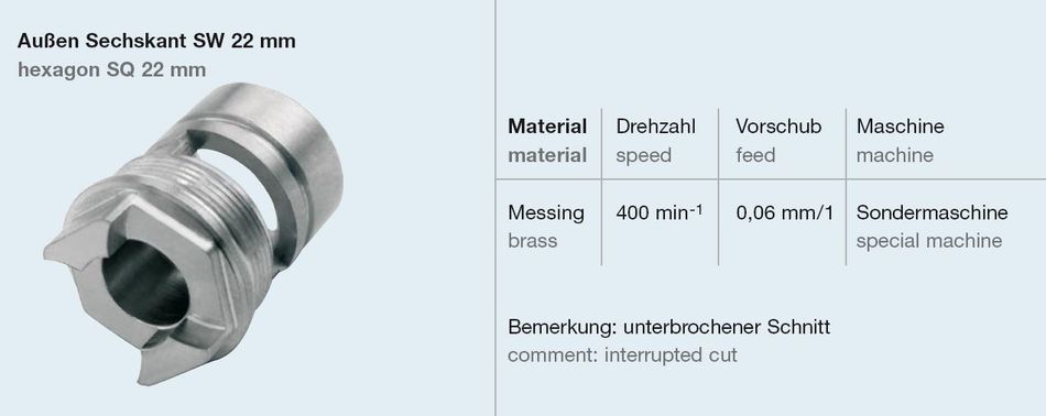
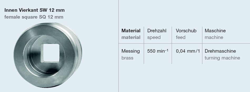
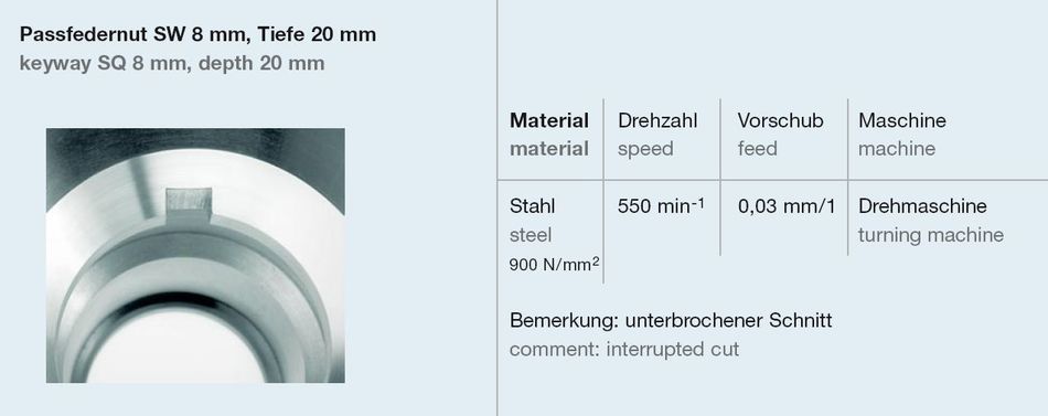
Processing examples


